Why is the cut edge rough and striated instead of smooth?
Updated:
Short answer
Striations are the fingerprint of an unstable melt front. Coarse, dragging lines mean the melt cannot keep up — usually speed, focus or gas dynamics. Fine even lines are normal and cannot be removed entirely; what you control is their depth and how far down the edge they start.
Reading the edge
| Symptom | Likely cause | First action |
|---|---|---|
| Lines curve backwards strongly at the bottom third; sometimes incomplete cut in corners. | Feed too high for the thickness | Reduce speed 10% and re-check; the melt front must reach the bottom of the kerf. |
| Smooth top band, rough lower half, wide top kerf. | Focus too high | Move focus down into the sheet; for nitrogen on thick stainless this can be several millimetres below the surface. |
| Rough edge with adhering melt, especially on the lower edge. | Gas pressure too low | Raise pressure to the range for the thickness and verify the nozzle is not enlarged. |
| One face of the part is noticeably rougher than the other. | Beam not centred in the nozzle | Re-centre the beam; on many heads this drifts after a collision or lens replacement. |
| Roughness appears in patches that match the flat and buckled areas. | Unstable standoff over a warped sheet | Improve clamping, cut smaller nests, or add tabs to reduce part movement and heat build-up. |
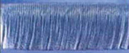
Photo diagnosis compares your edge against 47 catalogued defects. Open SBM Laser Help →
Or take it with you:
Related questions
- What edge roughness is achievable on 10 mm stainless?
- With nitrogen, correct focus and fresh consumables, a shop can expect a clean, uniformly striated edge that needs no rework for most fabrication. Mirror-smooth over the whole thickness is not a realistic target on 10 mm with a standard head.
- Do striations mean the part will fail inspection?
- Only against a specified roughness. If the drawing calls out Ra or a surface class, measure it — visual roughness alone is not a rejection criterion in most fabrication work.
- Can nesting order affect edge quality?
- Yes. Heat accumulation in a dense nest raises the local sheet temperature, which changes the melt behaviour on later parts. Spread the cutting sequence over the sheet if late parts look worse than early ones.